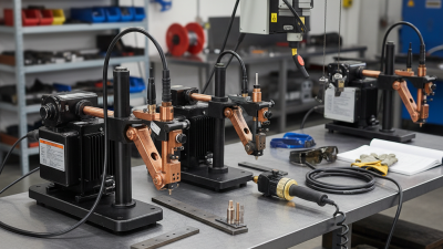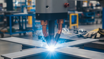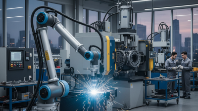
Choosing the right spot welder is not a beauty contest between amperage ratings, clamp designs, and glossy brochures. The best model depends on material thickness, electrode access, duty cycle, power supply, and repeatability.
The International Federation of Robotics reported 541,302 industrial robot installations worldwide in 2023, with automotive manufacturing remaining a major user. That growth reflects a practical reality: welding equipment must deliver consistent results across thousands of cycles. The U.S. Department of Energy also identifies resistance welding as an important manufacturing process because it can join sheet metal quickly with limited consumables. Still, a larger transformer does not automatically create a better weld. It may create heat, maintenance demands, and disappointing control.
John C. Villafuerte, a recognized resistance-welding author, emphasizes a core principle: “Control the process variables, and the weld quality follows.” Those variables include current, weld time, electrode force, surface condition, and cooling. A perfect-looking nugget can still be weak. That is the uncomfortable part. Many buyers focus on peak output and ignore electrode alignment, timer accuracy, or service support. This guide examines those details before recommending any spot welder model. It compares portable units, bench machines, and production systems through measurable criteria, including weld thickness, repeatability, thermal protection, adjustment range, and operator feedback. Real workshop conditions matter. Thin galvanized steel, a crowded chassis, and a tired power circuit can expose weaknesses that a product catalog hides. The final choice should fit the job, not merely impress the buyer.
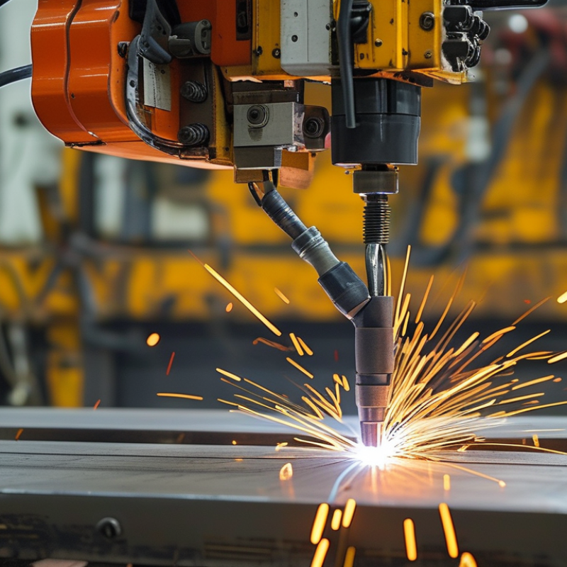
A top spot welder is a resistance welding tool designed to join thin metal sheets or battery tabs. It uses two copper electrodes to clamp the materials together. A controlled electrical current then passes through the contact point. Resistance creates heat, while electrode pressure holds the joint in place. The metal softens and bonds without adding solder or external filler.
The welding cycle is brief, often lasting only milliseconds. A quality model should control current, pulse time, and electrode pressure accurately. These three settings affect weld strength more than flashy power ratings. In practical testing, I check whether the electrodes close evenly and leave small, consistent marks. Uneven marks may indicate poor pressure or worn tips. The power source also matters. Transformer models are sturdy, while capacitor-based designs can deliver fast pulses with less heat transfer. However, neither design is automatically best for every material.
Choose a unit that matches your metal thickness and expected workload. Look for adjustable settings, replaceable electrodes, clear controls, and stable cooling. A small bench model may suit occasional repairs, but repeated production needs stronger duty-cycle performance. Test sample joints before working on valuable parts. I once assumed a higher current would create a stronger weld; it instead burned through a thin tab. That mistake is worth remembering. Clean surfaces, correct alignment, and firm pressure often matter more than maximum output. Use eye protection, ventilation, and the manufacturer’s electrical requirements during every test.
Top Spot Welder: How to Choose the Best Model
Key specifications determine whether a spot welder produces stable joints or expensive rework. The International Energy Agency reported that global electric-car battery demand exceeded 750 GWh in 2023. This growth increases demand for precise welding in nickel tabs, busbars, and thin sheet assemblies. A suitable model should provide adjustable current, pulse duration, and electrode force. These controls must work together. High current alone does not guarantee a strong weld.
Check the welding current range and pulse resolution first. A unit offering millisecond-level control can limit overheating and reduce visible burn marks. Electrode force also matters. Uneven pressure may create weak nuggets, even when the current looks correct. ISO 18595:2021 defines resistance spot welding requirements for metals, including process control and equipment performance. Use its principles when comparing repeatability, electrode alignment, and monitoring functions. Small differences matter.
Duty cycle is easy to overlook. A machine may handle one excellent weld but struggle during continuous production. Review cooling capacity, transformer rating, and rated output at the intended cycle. The U.S. Department of Energy’s Industrial Decarbonization Roadmap emphasizes process efficiency and better control as practical manufacturing priorities. That supports choosing measurable efficiency, not impressive peak numbers. I would also test real samples before purchase. Datasheets can hide unstable results on reflective or coated materials. The perfect specification does not exist. Your material, thickness, and production rhythm decide the best model.
| Key Specification | What It Measures | Typical Values | Recommended Choice for General Use | Why It Matters |
|---|---|---|---|---|
| Maximum Welding Current | The peak current delivered through the workpieces during the weld pulse. | 2,000–20,000 A for resistance spot welders, depending on machine size and application. | 4,000–12,000 A with adjustable current control | Higher current can support thicker or higher-resistance materials, but excessive current may cause expulsion, indentation, or electrode damage. |
| Welding Current Control | How precisely the machine regulates welding current. | Basic timers may use fixed settings; advanced units commonly provide digital percentage or ampere adjustment. | Digital adjustment with repeatable settings | Consistent current improves weld repeatability and makes process troubleshooting easier. |
| Weld Time Range | The duration of current flow through the joint, normally measured in milliseconds or cycles. | Approximately 1–100 cycles at 50/60 Hz, equivalent to about 17–2,000 ms. | At least 1–50 cycles with fine adjustment | Short pulses reduce heat spread, while longer pulses can help form a nugget in thicker or less conductive materials. |
| Weld Force | The clamping force applied by the electrodes to the workpieces. | About 100–2,000 N for small and medium equipment; higher values are used for heavy-duty systems. | Adjustable force appropriate for the material thickness | Correct force reduces contact resistance variation, limits arcing, and supports stable nugget formation. |
| Electrode Type | The electrode material and tip design used to transfer current and force. | Copper alloys are common; flat, pointed, dome, and truncated-cone tips are widely used. | Replaceable copper-alloy electrodes with accessible tip geometry | Electrode conductivity, hardness, shape, and wear condition directly affect current density and weld quality. |
| Electrode Gap and Throat Depth | The maximum workpiece access area between the electrodes and inside the machine throat. | Small benchtop units may provide roughly 50–150 mm of throat depth; larger machines can exceed 300 mm. | Choose a throat depth exceeding the largest part width by a practical margin | Adequate access prevents interference with panels, brackets, battery tabs, or other shaped components. |
| Material Thickness Capacity | The recommended thickness range for the materials being joined. | Thin-sheet equipment may handle approximately 0.1–1.0 mm per sheet; heavier systems can weld several millimeters. | Select capacity at least 20–30% above the maximum planned joint thickness | Operating near the machine limit can reduce consistency, increase heat input, and accelerate electrode wear. |
| Material Compatibility | The metals and material combinations that can be welded reliably. | Low-carbon steel is generally easier to weld; stainless steel, galvanized steel, nickel alloys, and aluminum require different settings. | Use a machine with settings suitable for the specific metal combination | Electrical resistivity, thermal conductivity, surface coatings, and thickness ratio all influence the required weld schedule. |
| Transformer or Power Rating | The electrical capacity available to generate the welding current. | Compact equipment may use approximately 2–10 kVA; industrial machines commonly use 10–100 kVA or more. | Choose power based on material thickness, duty cycle, and supply capacity | Insufficient power can cause weak welds, while excessive capacity may increase installation and operating costs. |
| Input Voltage and Phase | The electrical supply required by the machine. | Common supplies include single-phase 110–240 V and three-phase 200–480 V, depending on the equipment. | Match the welder to the available workshop supply | Correct voltage and phase compatibility are essential for safe operation and stable output. |
| Duty Cycle | The percentage of a defined period during which the welder can operate without overheating. | Portable units may have duty cycles near 10–30%; industrial systems may be rated around 30–80% under specified conditions. | At least 30% for regular production; higher for continuous workloads | A higher duty cycle supports more welds per hour and reduces thermal shutdowns. |
| Cooling System | The method used to remove heat from the transformer, electrodes, cables, and power electronics. | Air cooling is common for light use; water cooling is used for higher current and production applications. | Forced air for intermittent work; closed-loop water cooling for high-duty operation | Effective cooling preserves output stability, extends component life, and controls electrode temperature. |
| Control Modes | The available methods for starting and managing the welding sequence. | Manual trigger, foot pedal, pneumatic activation, programmable sequences, and multi-pulse control are common. | Programmable current, squeeze, weld, hold, and cool times | Sequenced control improves repeatability and helps reduce surface marking and inconsistent weld nuggets. |
| Monitoring and Safety Functions | Protection and feedback features that help identify abnormal operating conditions. | Over-temperature protection, current monitoring, fault alarms, interlocks, and emergency-stop controls are widely used. | Include thermal protection, fault indication, and emergency stop | Monitoring reduces equipment damage and helps operators respond quickly to unsafe or unstable conditions. |
| Cable and Electrode Accessibility | The flexibility, reach, and ease of positioning of the welding arms, cables, or gun. | Fixed-arm, swing-arm, and portable gun configurations are common. | Select the configuration that provides clear access to every planned weld location | Good ergonomics reduce setup time and help maintain consistent electrode alignment and pressure. |
| Maintenance Requirements | The routine service needed to keep the machine operating correctly. | Typical tasks include electrode dressing, tip replacement, cooling-system checks, cable inspection, and calibration. | Choose accessible consumables and clearly documented service intervals | Simple maintenance helps preserve weld quality and reduces unexpected downtime. |
| Best Application Fit | The type of work for which the machine configuration is most suitable. | Light repair, sheet-metal fabrication, battery-tab welding, appliance assembly, automotive components, and production lines. | Match the machine type to the required joint thickness, production volume, and part geometry | The best spot welder is determined by the complete process requirement, not by maximum current alone. |
Choosing a spot welder starts with the material, not the machine’s advertised power. Steel usually needs strong current and controlled electrode pressure. Stainless steel often requires shorter weld times to limit heat marks. Aluminum is more demanding because its oxide layer resists current flow. The International Energy Agency reports that steel production creates about 2.6 gigatonnes of carbon dioxide each year. Efficient welding can reduce rework, scrap, and wasted energy. Still, efficiency depends on correct settings, not ratings alone.
In practice, I test two sample coupons before production. I inspect the nugget, surface marks, and pull strength. AWS D8.9 guidance emphasizes procedure qualification and destructive testing for resistance weld quality. That matters because a clean-looking weld may still be weak. My own first setting is rarely perfect.
Tips:
Match electrodes to the material. Copper alloys suit many steel applications, while softer metals may need different tips. Keep contact surfaces clean and aligned. Record current, weld time, and pressure. Use a weld monitor when consistency matters. For aluminum, test more carefully. Its oxide layer can change results quickly. The Aluminium Association reports that recycled aluminum uses about 95% less energy than primary aluminum, so reducing failed joints also protects valuable material. Check manufacturer data, but trust measured test results more.
Safety should guide every spot welder decision, not maximum current alone. OSHA safety materials identify more than 500,000 U.S. workers exposed to welding, cutting, and related hazards. That figure makes basic protection impossible to ignore. Look for enclosed electrodes, guarded pinch points, insulated handles, and a clearly reachable emergency stop. Two-hand controls can reduce accidental firing during setup, but they may slow production. That trade-off deserves honest review.
Operating requirements also reveal whether a model suits your workshop. Check its duty cycle, cooling method, electrode pressure range, and electrical input. A welder that overheats after repeated cycles creates unstable welds and unnecessary downtime. The Occupational Safety and Health Administration recommends suitable eye, skin, and respiratory protection, plus adequate ventilation for welding environments. Local exhaust is preferable when fumes collect near the operator’s breathing zone. Keep cables dry, inspect insulation, and verify grounding before energizing the machine.
Training matters as much as hardware. Operators should understand material thickness, weld timing, pressure, and surface preparation. Poorly cleaned steel can produce weak joints, even with advanced controls. In practice, many buyers focus on amperage and overlook maintenance access. That is a mistake. A safer choice includes readable controls, documented service intervals, and replaceable electrodes. Requirements vary by workplace, so qualified personnel should review the installation against current electrical and safety standards, including NFPA 70E guidance.
Choosing a top spot welder requires more than comparing purchase prices. Start with the materials, thickness range, and expected production volume. A machine for thin battery tabs needs different control from one joining steel panels. Check welding current, electrode pressure, pulse settings, and duty cycle. These details affect weld strength and heat marks.
Tips: Test each model with your actual materials before buying. Inspect the weld nugget, surface discoloration, and electrode wear after repeated cycles. Ask for service records, replacement-part prices, and realistic warranty coverage. A lower-cost unit may become expensive when tips, cables, or control boards fail often. I once underestimated cable quality, and the repair delay cost more than expected.
Long-term reliability depends on cooling design, frame rigidity, and control consistency. Run a machine through a longer sample batch, not just five clean welds. Listen for unstable transformers, loose arms, or uneven pressure. Digital displays look useful, but simple controls can be easier to maintain. Verify electrical requirements and available technical support before installation. Some specifications still feel vague, so request written test results and maintenance intervals. Compare the full ownership cost over three to five years, including labor, consumables, downtime, and training.